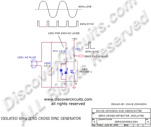
50hz To 60hz Frequency Converter Circuit Diagram
The subtle hum of electricity powering our lives operates on a language of cycles, measured in hertz (Hz). This seemingly innocuous frequency becomes a critical point of divergence when dealing with electrical systems designed for different standards, specifically 50Hz and 60Hz. A divergence necessitating the 50Hz to 60Hz frequency converter circuit, a piece of engineering vital for ensuring compatibility and preventing potential equipment damage across global borders.
At its core, the 50Hz to 60Hz frequency converter circuit addresses a fundamental incompatibility: Electrical grids worldwide operate at different frequencies, with 50Hz being common in Europe, Asia, and parts of Africa, while 60Hz is the standard in North America. This seemingly small difference has significant implications, as electrical devices are designed to operate optimally at their intended frequency.
This article delves into the intricacies of this essential circuit, exploring its design, function, and the critical role it plays in enabling seamless operation of electrical equipment across different frequency standards. Furthermore, it examines the benefits, challenges, and future trends shaping the landscape of frequency conversion technology.
Understanding the Need: Frequency Standards and Their Implications
The difference between 50Hz and 60Hz power lies in the rate at which alternating current (AC) completes its cycles per second. Electrical devices, particularly motors and transformers, are designed with specific inductance and impedance values optimized for their intended frequency.
Operating a 50Hz device on a 60Hz supply, or vice versa, can lead to several issues. Overheating, reduced efficiency, and even catastrophic failure are among the potential consequences.
Motors, for instance, will generally run faster on a higher frequency supply. This can lead to premature wear and tear, potentially damaging the connected equipment. Transformers also suffer, with increased eddy current losses and possible saturation of the core.
The 50Hz to 60Hz Frequency Converter Circuit: Design and Function
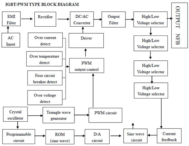
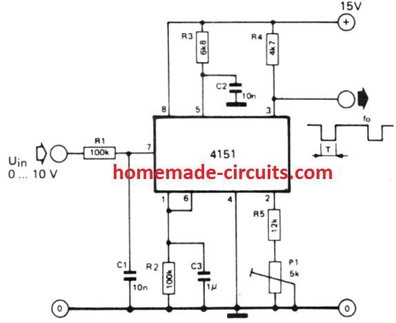
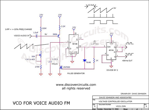
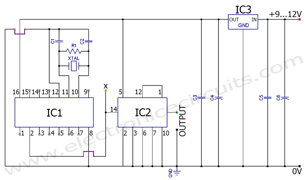
The 50Hz to 60Hz frequency converter circuit comes in several forms, each with its own advantages and disadvantages. Traditional methods often involve rotary converters, essentially a motor-generator set where a motor runs on 50Hz and drives a generator producing 60Hz.
Modern solutions, however, predominantly utilize solid-state converters, leveraging power electronics components such as insulated-gate bipolar transistors (IGBTs) and silicon-controlled rectifiers (SCRs). These solid-state converters offer higher efficiency, smaller size, and greater control.
Key Components and Working Principle
Solid-state converters typically operate in a two-stage process. The first stage involves rectification, where the incoming 50Hz AC power is converted into DC power. The second stage uses an inverter to generate a 60Hz AC waveform from the DC power.
Advanced control algorithms, often implemented with microcontrollers or digital signal processors (DSPs), precisely control the switching of the power electronic devices, ensuring a stable and accurate 60Hz output. Precise control is key to minimizing harmonic distortion and maintaining the quality of the output waveform.
Filters are crucial for removing unwanted harmonics generated during the switching process, ensuring a clean and sinusoidal 60Hz output. These filters are typically designed using inductors and capacitors, tuned to attenuate specific harmonic frequencies.
Applications and Benefits
The applications of 50Hz to 60Hz frequency converters are widespread, spanning industries from manufacturing to telecommunications. They are essential for operating equipment designed for one frequency standard in regions with a different standard.
Marine vessels are a prime example, often needing to power equipment designed for 60Hz while docked in ports with 50Hz power. Similarly, industries importing machinery from different countries rely on converters to ensure compatibility.
The benefits of using frequency converters extend beyond mere compatibility. They can also improve the performance and lifespan of equipment by providing a stable and controlled power supply.
Challenges and Considerations
Designing and implementing efficient and reliable frequency converters presents several challenges. One of the main concerns is dealing with harmonic distortion, which can negatively impact the performance of connected equipment.
Heat dissipation is another critical consideration, as power electronic components generate significant heat during operation. Effective cooling strategies, such as heat sinks and forced air cooling, are essential to prevent overheating and ensure long-term reliability.
The cost of frequency converters can also be a barrier, especially for large-scale applications. However, the long-term benefits of protecting equipment and ensuring optimal performance often outweigh the initial investment. Cost-benefit analysis is an important step during the design phase.
Future Trends and Innovations
The field of frequency conversion is continuously evolving, driven by advancements in power electronics and control technologies. Silicon carbide (SiC) and gallium nitride (GaN) devices are increasingly being used in converters, offering higher efficiency and switching speeds.
Improved control algorithms, incorporating artificial intelligence (AI) and machine learning (ML), are being developed to optimize converter performance and adapt to varying load conditions.
"These advancements promise to create even more efficient, reliable, and compact frequency converters in the future," states a recent report by IEEE.
Furthermore, the integration of frequency converters with smart grids and renewable energy systems is gaining traction, enabling seamless integration of diverse power sources.
Conclusion
The 50Hz to 60Hz frequency converter circuit is a vital component in our increasingly interconnected world, enabling the seamless operation of electrical equipment across different frequency standards. Its importance will only continue to grow as globalization increases and the demand for efficient and reliable power conversion solutions intensifies.
From marine vessels traversing global waters to factories importing machinery from across continents, this seemingly simple circuit plays a critical role in keeping our world powered and connected. Continued innovation in power electronics and control technologies will undoubtedly lead to even more advanced and efficient frequency conversion solutions in the years to come.