How To Make Internal Threads In Solidworks

So, You Wanna Tap That (Virtually, of Course)?
Let's talk about making internal threads in SolidWorks. It's like trying to parallel park a spaceship – looks easy on paper, right?
Spoiler alert: it's not *always* sunshine and rainbows. But don't worry, we'll get through this together. I promise, no therapy required (probably).
The "Cosmetic Thread" Route: My Unpopular Opinion
Okay, brace yourselves. I'm about to say something that might get me banned from every SolidWorks forum ever.
I think, and this is just me, that the Cosmetic Thread feature is…underrated. There, I said it!
Sure, it doesn't *actually* cut the thread into your model. It's just a visual representation, a pretty lie, if you will.
But honestly, how often do you *really* need the actual geometry? Are you 3D printing a fully functional screw? If so, carry on my friend!
For most of us making drawings, generating BOMs, or just generally showing off our designs, a Cosmetic Thread is perfectly adequate.
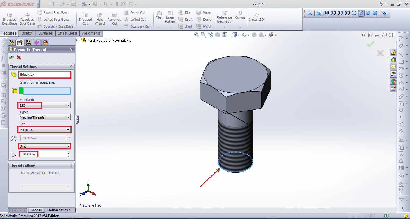
Want to give it a whirl? Find your hole. Click "Insert". Navigate to "Annotations". Select "Cosmetic Thread".
Now, twiddle some knobs, pick the correct standard and size, and BAM! Threaded hole, visually speaking.
Pro Tip: Remember to update your drawing templates to automatically show the thread callout. Saves time. Saves sanity.
The "Hole Wizard" is Your Friend (Sometimes)
Ah, the Hole Wizard. It's like that overly enthusiastic friend who tries a little too hard.
It promises so much! Standard holes, counterbores, countersinks…and yes, even threaded holes!
The Hole Wizard will, in fact, create a feature that represents a tapped hole.
However, similar to the cosmetic thread, it's often a *representation* of the hole. The geometry is often not a real thread cut.
You can choose a tap drill size and specify the thread standard. Solidworks adds the hole and gives you the annotation.
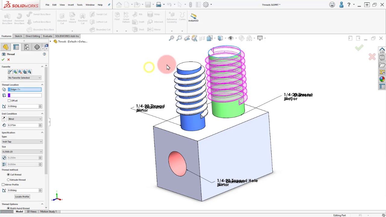
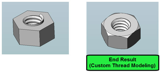
When You Absolutely, Positively Need Real Threads (And I Mean *Really*)
Alright, sometimes you just need to cut real, honest-to-goodness threads. I get it.
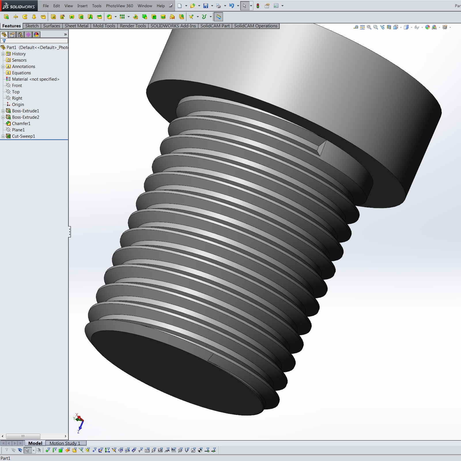
This usually involves a helix, a profile, and the *Swept Cut* feature. Sounds fun, right?
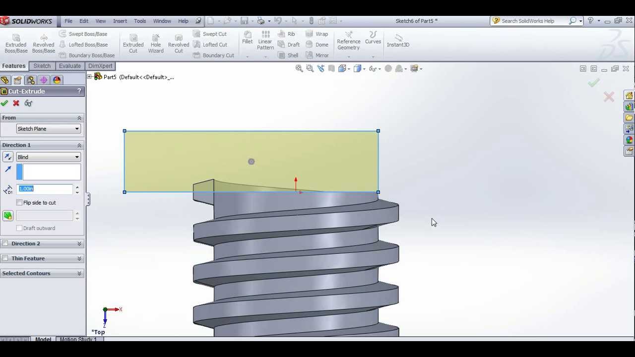
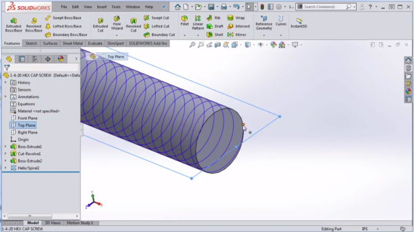
First, create a sketch with a circle where you want the hole. Extrude it to the desired depth.
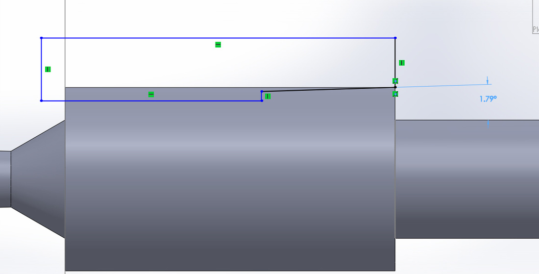
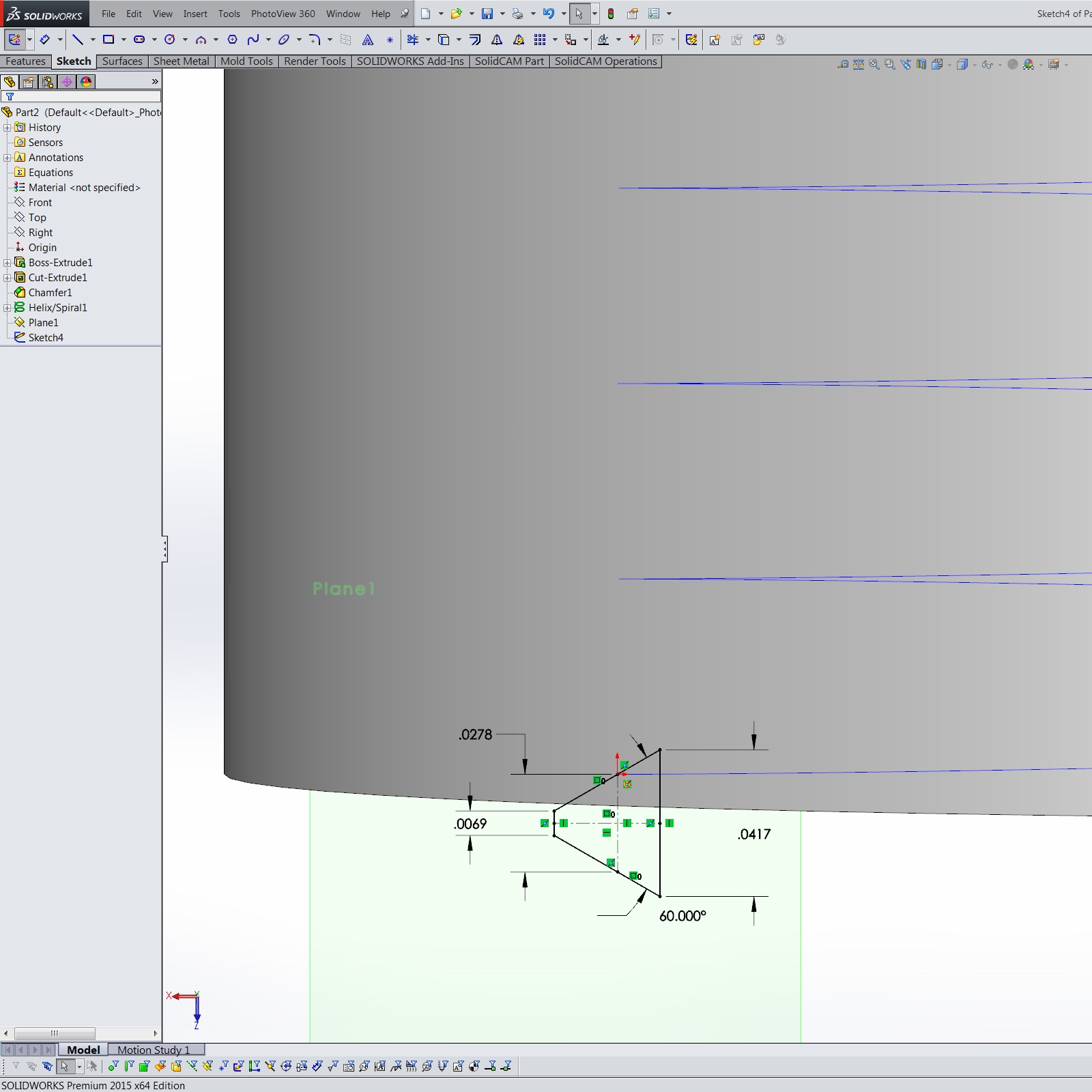
Then, sketch a profile of your thread. This is where things get a little hairy (pun intended!). You'll need to accurately define the thread form.
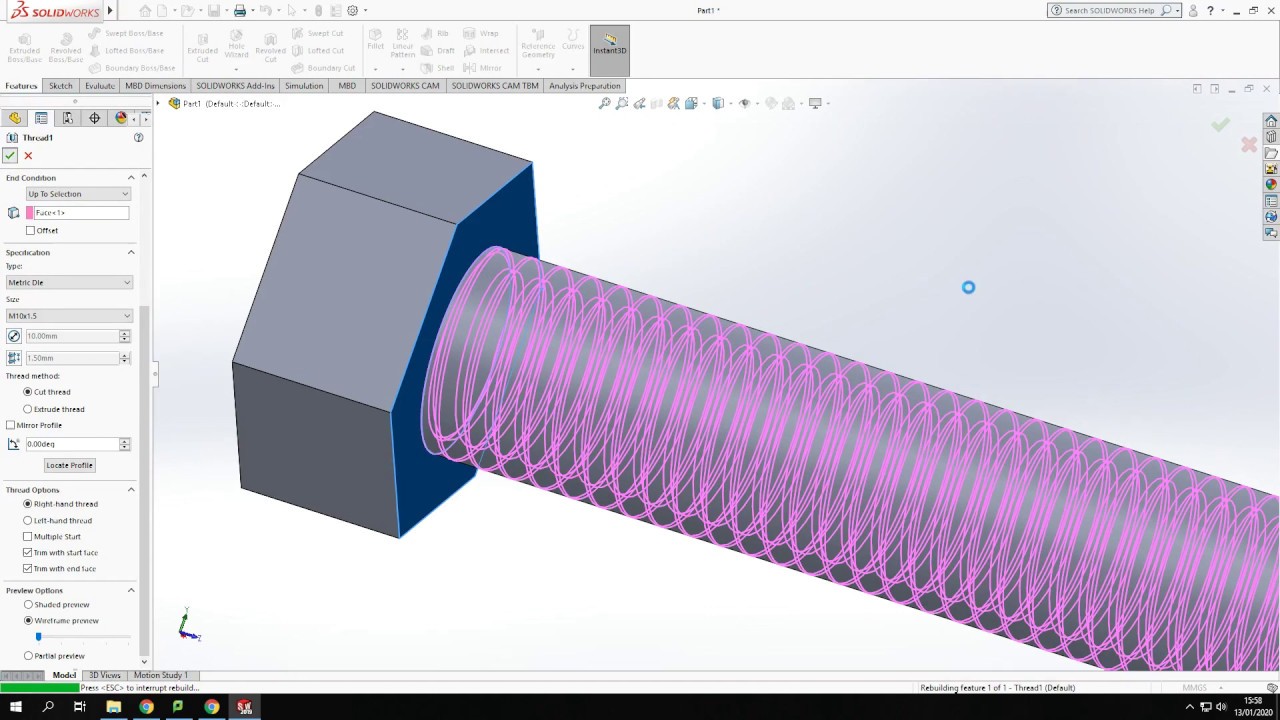
Next, create a helix that follows the path of the thread. This is usually done using the "Curve" > "Helix and Spiral" command.
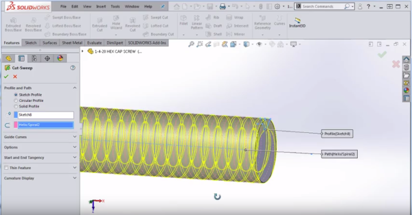
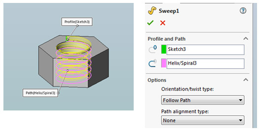
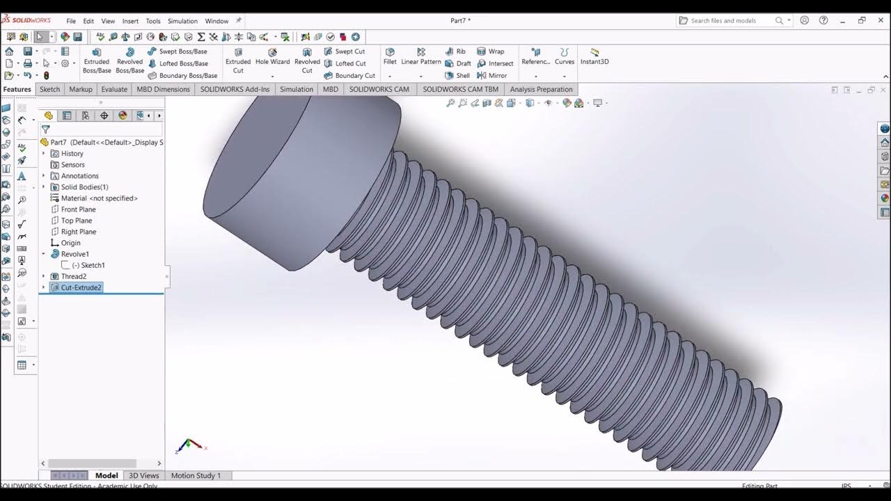
Finally, use the *Swept Cut* feature to sweep the thread profile along the helix. Boom! Real threads!
Now, was it worth it? Probably not, unless you're building a rocket engine or something equally hardcore.
Just kidding! (Mostly.) Sometimes the extra detail is necessary. But be prepared for longer rebuild times.
Seriously, your computer might hate you a little bit afterwards. Consider yourself warned.
Final Thoughts: Keep It Simple, Silly!
My advice? Start with the Cosmetic Thread. If that doesn't cut it (again, pun intended!), explore the Hole Wizard.
And only resort to the Swept Cut method if your job *absolutely* demands it. Your sanity will thank you.
Happy threading! May your holes be perfectly sized and your assemblies always fit together just right.